 Loading... Please wait...
Ashtray, Cupholders, Amrest, Console, Glove Box
CLICK HERE FOR FULL PDF VERSION
Please give credit where credit is due! This DIY was completed ENTIRELY by the hardest
working VW Vortex moderator on the site!! Gary Thompson, Ph.D. - vortex ID VGRT6, email
address vgrt6@yahoo.com. Please make sure to say thanks to Gary, and if you ever see him at
a bar, buy em a beer. These DIY's are more complete than anything Bentley has ever written!!
PART I :
STEPS FOR REMOVING REAR ASHTRAY & CUP HOLDER, CENTER ARMREST, EBRAKE
CONSOLE, FRONT ASHTRAY, LOWER CENTER CONSOLE AND GLOVE BOX
PART II :
STEPS FOR REMOVING DRIVER'S SIDE DASH TRIM, BRAKE-LIGHT SWITCH,
RADIO/CUBBY HOLE, FRONT CUPHOLDER AND RADIO/HVAC TRIM CAGE
The following outlines the procedure for removing the above items on a MKIV Jetta and Golf/GTI.
The procedure was based on a 99.5 Jetta GLS VR6 with a manual transmission - it may be slightly
different on later-models cars (those with no rear cup holder) and all models with automatic
transmission. Please do these procedures at your own risk and be ready to make small
adjustments while doing them. Also, please be observant while removing parts so that they go
back together correctly.
- To remove the rear ashtray and cupholder, follow steps 1 through 7.
- To remove the center armrest, follow steps 8 through 10.
- To remove the e-brake console, follow steps 1 through 17.
- To remove the front ashtray, follow steps 18 through 24.
- To remove the lower center console, follow steps 1 through 35.
- To remove the glove box, follow steps 1 through 42.
____________________________________________________________________
STEPS:
1. Slide the driver's and front passenger's seats completely forward.
2. Open rear ashtray and remove red insert as shown in picture below.
10/29/13 Please give credit where credit is due
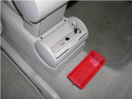
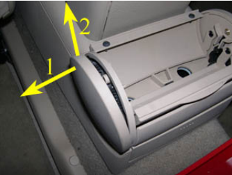
3. Remove the two sides to the rear ashtray as shown in the picture below. Pry the top of the
ashtray side off of the ashtray housing (1). Once this is done, pull upwards on the ashtray side (may
have to pull hard) to remove it (2).
4. The picture below illustrates how the top and bottom of the ashtray sides are connected to the
ashtray.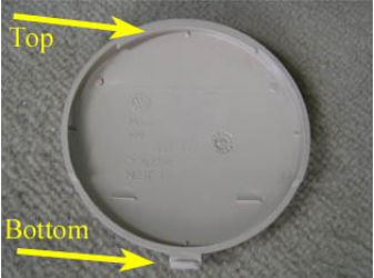
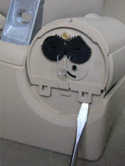
5. Remove the rear ashtray housing by carefully prying up the two tabs on each side with a
screwdriver, as shown in the picture below. Be careful not to break the tabs while doing this - they
are somewhat difficult to get off.
6. To remove the rear cup holder (if applicable), push down the two retaining tabs indicated by the
arrows in the picture below.
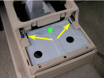
7. Slide the rear cupholder out of the e-brake console as shown in the picture below.
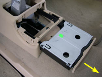
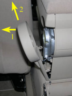
8. Remove the driver's side of the armrest trim as shown in the picture below. First pull the top of
the trim towards the driver's side (1) and then pull upwards at an angle to remove (2).
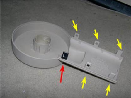
9. Be careful doing the above. The trim piece is held in by 6 tabs as shown in the picture below
(arrows). I've removed this piece enough times that I've partially broken one of the tabs (red arrow).
You can use a thin screwdriver protected by a thin rag to help ease the tabs out.
10. Remove the 13mm bolt in the picture below to remove the armrest. Once the bolt is out, you
may need to wiggle the armrest back and forth to get it free - then move it up to remove.
11. Remove the two T20 Torx screws indicated by the arrows in the picture below.
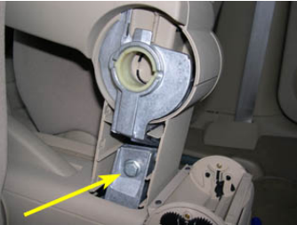
12. Slide the driver's and front passenger's seats completely backward. Pry out the trim tab on
both sides of the e-brake console indicated by the arrow in the picture below.
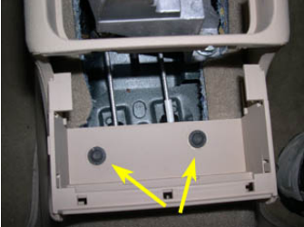
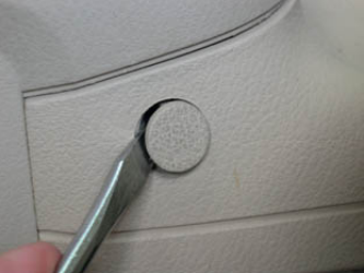
13. This is easily done with a screwdriver, as shown below.
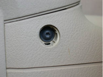
14. Remove the T20 Torx screws behind the tabs, as shown below.
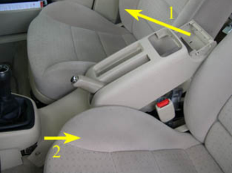
15. Pull up the emergency brake handle as high as it will go - the higher it is, the easier the next
step will be. Remove the e-brake console by (1) raising the rear of the console relatively high (see
picture below for approximate position) and then (2) sliding the front of the console out from under
the lower center console (where the shifter is). When the front of the e-brake console is free, slide
the console up and over the e-brake handle. This may take a few attempts - it's somewhat difficult
to free the front of the e-brake console from under the lower center console.
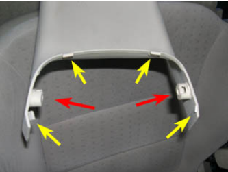
16. The image below shows the 4 tabs (yellow arrows) and two posts (red arrows) that make it
difficult to release the front of the e-brake console from under the lower center console.
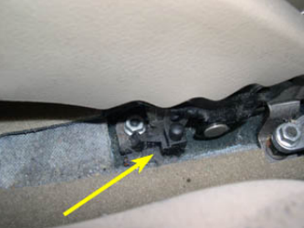
17. The picture below shows the position of the e-brake microswitch. It just clips onto the e-brake
support and can be easily removed.
18. Slide open the front ashtray lid and remove the red insert seen in the picture below. (I apologize
for the detritus - I should have done some detailing before I took the pics.)
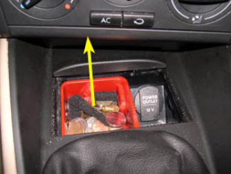
19. Remove the small trim piece just below the A/C controls (or Climatronic if that's what you have)
by pulling it towards the rear of the car, as shown below. While this step is not absolutely
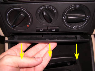
necessary, it makes the removal of the front ashtray significantly easier.
20. Remove the T20 Torx screw at the bottom of the front ashtray indicated by the arrow in the
picture below.
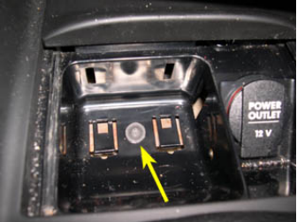
21. Using two screwdrivers (only one is shown), pull the two tabs indicated by the arrows in the
picture below up simultaneously (1) and slide the ashtray toward the front of the car (into the center
console) approximately 1/2" (2). Be careful to only pry the tabs up slightly as they break very easily
- I managed to break the left one in the picture. They only need to come up enough to clear the
metal bracket underneath that the ashtray attaches to.
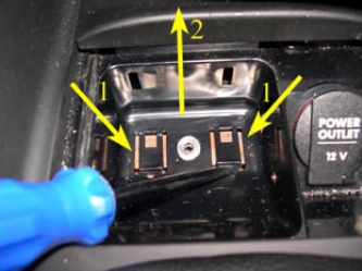
22. Raise the rear edge of the ashtray upwards, as shown below, making sure the two tabs on the
edge of the ashtray clear the center console (1). Once they're clear, slide the ashtray towards the
rear of the car and out of the center console (2).
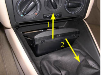
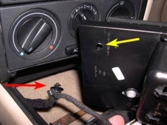
23. Disconnect the power wire for the 12v outlet from the ashtray by removing the wire retaining
clip (red arrow) from the hole in the bottom of the ashtray (yellow arrow), as shown below.
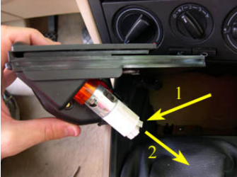
24. Disconnect the power wire from the 12v outlet by pressing in the white tab (1) and pulling the
harness connector out (2), as shown below.
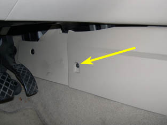
25. Remove the T20 Torx screw from each side of the front of the lower center console in the
footwell, as shown below.
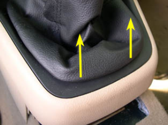
26. Disconnect shifter boot from lower center console by pulling up on the rear edge of the boot
support, as shown below.
27. Slide the boot all the way up and out of the way and remove the foam piece that surrounds the
shifter mechanism inside the lower center console, as shown below.
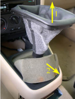
28. At this point, attempt to slide the lower center console backward, disconnecting it from the
main (vertical) center console. If you are able to remove the lower center console without any
difficulty, goto step 34 (ignore steps 29 through 33 - they are not applicable to your model year).
29. If you can't slide the lower center console backward easily, there is a good chance that there is
a small metal bracket in the way, indicated by the yellow arrow in the image below. From what I can
gather, this bracket only interferes with the lower center console removal on early-model MKIV
cars. To remove the lower center console, the bracket must be removed - this is by far the most
difficult step of the entire DIY.
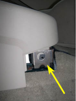
30. Begin by removing the 10mm nut (right) which holds the bracket down, as shown below.
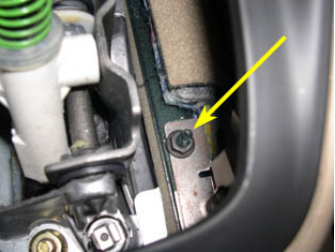
31. The lower center console sits directly above the nut, so a flex-joint socket or something similar
is needed to remove the nut. I put a 10mm socket onto the nut and then used a socket driver which
was not fully inserted into the socket and at an angle to remove the nut (see picture below).
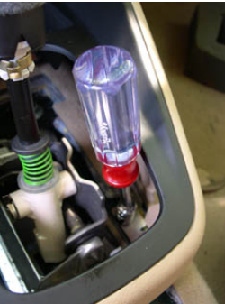
32. Do the same for the left bracket nut, which is shown below.
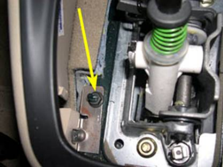
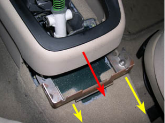
33. When both 10mm nuts are off, raise the front of the bracket over the posts that the nuts were on
and then slide the bracket backward and out from underneath the lower center console (yellow
arrows in picture below). This is difficult to do due to the limited amount of space under the
console. Once the bracket is out, you should be able to slide the lower center console backward
(red arrow in picture below) and few inches and then up and over the shifter.
34. The lower center console has two plastic fingers approx. 1.5" long which protrude from the front
edge (red arrows in picture below points to driver's side finger).
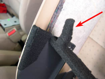
35. These fingers insert into corresponding holes in the bottom of the main center console (yellow
arrows), as shown below. The fingers (above) are normally bare plastic, but I covered them with felt
to prevent the fingers from rubbing in the holes - this caused a loud creaking when side pressure
from my knee was applied to the lower center console while driving. This cured the problem. I
recommend that you do this if you have the lower center console removed.
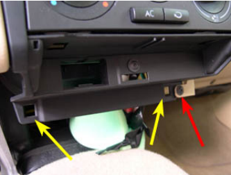
36. The hidden/mystery 8th screw that holds the glove box in can also be seen in the above picture
(indicated by the red arrow). Remove this screw if you plan on removing the glove box.
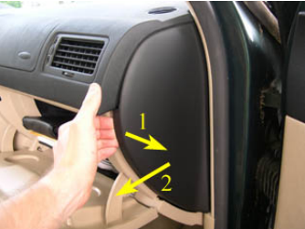
37. Open the front passenger door, open the glove box and pull the rear edge of the side
dashboard panel out and then towards the rear of the car, as shown below. It's easier if you use
two hands, but I needed one to hold the camera.
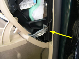
38. Remove the T25 Torx screw indicated by the yellow arrow in the picture below.
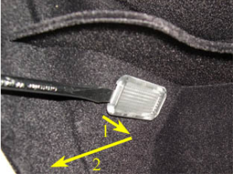
39. Use a screwdriver to carefully pry out the rear of the light in the glove box(1) and then slide it
towards the rear of the car to get it out (2), as shown below.
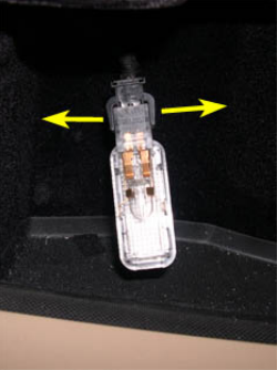
40. Disconnect the harness connector from the light by pulling the two tabs apart simultaneously, as
shown below. Once disconnected, push the wire back into the hole that the light occupies.
41. Remove the three T20 Torx screws on the bottom of the glove box, as shown below.
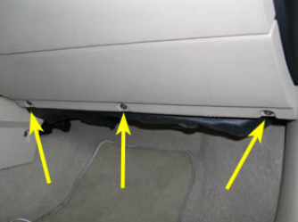
42. Remove the three T20 Torx screws on the top of the glove box, as shown below. Pull the glove
box out and disconnect the microswitch for the glove box light from near the driver's side hinge.
The glove box can now be removed from the car.
NOTE: Due to length restrictions, this DIY is continued in another thread - PART II ...
REASSEMBLY TIPS
A. When reinstalling the lower center console, make sure the front sides of the console slide into
the brackets indicated by the yellow arrow in the picture below. It may take a few attempts to get
both sides to catch. You'll see if/when you try it.
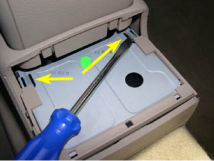
B. When reinstalling the rear cupholder, make sure to pry up the retaining tabs with a screwdriver,
as shown below, or the cupholder may slide back out.
C. The rest of the reinstallation should be the exact opposite of the above - follow steps 1 through
40 in reverse.
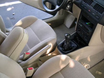
Here's a pic of everything put back together, i.e., the above directions do work!
Let me know if you have any questions.
As always, do this procedure at your own risk. I am not responsible for any mistakes in
the procedure or those that you make while performing it.
PART II: STEPS FOR REMOVING DRIVER'S SIDE DASH TRIM, BRAKE-LIGHT SWITCH,
RADIO/CUBBY HOLE, FRONT CUPHOLDER AND RADIO/HVAC TRIM CAGE
The following outlines the procedure for removing the above items on a MKIV Jetta and Golf/GTI.
This DIY (PART II) is a continuation of PART I - I had to break the DIY up into two threads since the
single-thread version far exceeded the 20000 character limit for a single post. It also helps make
the DIY more searchable, since the parts covered in PART II will be listed in the thread title.
The procedure below was based on a 99.5 Jetta GLS VR6 with manual HVAC controls - it may be
slightly different on later-models cars and on those with CLIMATRONIC. Please do these
procedures at your own risk and be ready to make small adjustments while doing them. Also,
please be observant while removing parts so that they go back together correctly.
Some of the pictures in PART II of the DIY were taken without performing all of the steps in PART I
(I had reassembled the items in PART I and did not want to disassemble them again), so items
that should have already been removed may appear in some of the pictures. Please disregard the
discrepancies in continuity. If you follow the steps as written and only focus on the piece(s) of
interest in the photos below, you should have no problems completing all of the disassembly steps.
Thanks to nimhrat for providing the photos associated with the removal of the OEM radio (I have an
aftermarket headunit) and the flap on the new style front cupholder - they were taken from the
following thread - http://forums.vwvortex.com/zerothread?id=961773). Also, thanks to
images@digitallattice.bc.ca for the image of the single-DIN support tray in step 54.
- To remove the driver's side trim, follow steps 43 through 47.
- To remove the brake light switch, follow steps 43 through 50.
- To remove the radio and cubby hole (if applicable), follow steps 51 and 52.
- To remove the front cupholder, follow steps 57 through 58.
- If you are doing a trim swap and need to remove the radio/HVAC trim cage and swap the
cupholder flap, complete PART I of this DIY and then follow steps 43 through 61.
____________________________________________________________________
STEPS:
Before beginning PART II, perform the necessary steps from PART I, as outlined above.
43. Remove the driver's side dash trim by opening the fuse panel access door on the driver's side
of the dashboard. The switchblade key is useful for this step, as shown below.
10/29/13 Please give credit where credit is due
gruvenparts.com/website/diys/Interior - Ashtray, Cupholders, Amrest, E brake, Consoles, Glovebox, Trim.htm 21/30
44. Once the fuse panel access door is open pull off the trim piece which contains the door using
both hands, as shown below (only one hand is shown since I needed the other one to take the
picture).
10/29/13 Please give credit where credit is due
gruvenparts.com/website/diys/Interior - Ashtray, Cupholders, Amrest, E brake, Consoles, Glovebox, Trim.htm 22/30
45. The picture below shows why the fuse panel trim piece can be difficult to remove - it is held on
by 3 clips (yellow arrows) and 1 tab (red arrow).
10/29/13 Please give credit where credit is due
gruvenparts.com/website/diys/Interior - Ashtray, Cupholders, Amrest, E brake, Consoles, Glovebox, Trim.htm 23/30
46. Remove the dash trim piece to the lower left of the steering wheel by removing the two T20
Torx screws at the bottom of the piece (indicated by the arrows in the picture below) and pulling the
trim piece off of the dash.
47. Remove the dash trim piece to the lower right of the steering wheel in the same manner.
Remove the two T20 Torx screws (indicated by the arrows in the picture below) and pull the trim
piece off of the dash.
48. If you want to access the brake light switch or anything else up under the dash, remove the
panel above the driver's side footwell by uncliping the front of the panel (pull the area indicated by
the yellow arrow in the picture below toward the rear of the car) and then sliding the panel out from
under the dash. Note that the edge of the panel closest to the front of the car is secured by two
horizontal slots (white plastic), indicated the red arrows in the picture below. This step is not
10/29/13 Please give credit where credit is due
gruvenparts.com/website/diys/Interior - Ashtray, Cupholders, Amrest, E brake, Consoles, Glovebox, Trim.htm 24/30
necessary for the further disassembly of the center console/radio/HVAC area. If you are not
accessing the brake light switch or anything else up under the dash, goto step 51 (ignore steps 49
and 50).
49. The picture below shows the location of the brake light switch, which is indicated by the arrow.
This switch often malfunctions and need to be adjusted or replaced. To remove the switch from it's
bracket, rotate the switch CCW (35-45° or 90°, depending on which version you have) and slide it
towards the rear of the car. DO NOT PRESS DOWN THE BRAKE PEDAL WHILE DOING THIS
OR THE INTERNAL MECHANISM OF THE SWITCH (on the most recent versions) WILL
BREAK!!! To install a new brake light switch (without destroying it as many people have), follow the
directions I posted in the following DIY - Installing a new brake light switch (without destroying it!).
50. To disconnect the brake light switch from it's harness connector, push the two tabs (indicated
by arrows in the picture below) toward each other and pull the harness connector off of the switch.
10/29/13 Please give credit where credit is due
gruvenparts.com/website/diys/Interior - Ashtray, Cupholders, Amrest, E brake, Consoles, Glovebox, Trim.htm 25/30
51. The next step is the removal of the radio - the directions for this depend on what type of radio
you have. If you have a stock VW radio, insert the radio removal keys into the vertical slots at the
edge of the radio face (indicated by the arrows in the picture below), press the keys in all the way
while at the same time pulling back on the radio to slide it out of it's DIN slot. Once it's out,
disconnect the power, speaker and antenna connections behind the radio.
52. If you have a double-DIN radio, remove the double-DIN unit as described above and goto step
55. If you have separate single-DIN radio and CD units, remove both units as described above and
continue on with step 53. If you have a single-DIN radio and a cubby hole, remove the radio as
described above. Next pull the cubby hole unit toward the rear of the car to remove it - it's secured
by a single tab at the back (edge closest to front of car) - and then continue on with step 53. If you
have an aftermarket head unit, remove the headunit per the manufacturer's instructions and also
remove the DIN cage that the headunit slides into.
53. Remove the support tray between the two single-DIN slots, shown in the picture below.
10/29/13 Please give credit where credit is due
gruvenparts.com/website/diys/Interior - Ashtray, Cupholders, Amrest, E brake, Consoles, Glovebox, Trim.htm 26/30
54. The DIN support tray is secured with a clip on either side (yellow arrows in picture below) and a
tab at the rear (red arrow in picture below). Undo the clip on both sides of the tray (may need to use
a screwdriver or other tool - I can't remember) and then pull the tray out to disconnect the tab at the
rear.
55. Remove the trim from around the HVAC controls using a screwdriver or other suitable tool, as
shown below.
10/29/13 Please give credit where credit is due
gruvenparts.com/website/diys/Interior - Ashtray, Cupholders, Amrest, E brake, Consoles, Glovebox, Trim.htm 27/30
56. Remove the four T20 Torx screws at the corners of the HVAC controls, as indicated by the
arrows in the picture below.
57. Open the front cupholder flap while keeping the actual cupholder tucked away in it's slot. To do
this, push on the flap to release the cupholder, push the cuphloder back in but don't fold the flap
down, as shown below. The cupholder unit is secured to the cage surrounding the
cupholder/radio/HVAC controls by two tabs, indicated by the arrows in the picture below. Move the
tabs toward each other simultaneously using a screw driver and then slide the cupholder unit out.
This is actually much easier then it sounds - move one clip to the side and then pull that side of the
cupholder unit out a little to keep the clip from springing back. Carefully move the clip on the other
side and then pull the unit out.
58. The picture below shows one of the clips that secures the cupholder in place.
10/29/13 Please give credit where credit is due
gruvenparts.com/website/diys/Interior - Ashtray, Cupholders, Amrest, E brake, Consoles, Glovebox, Trim.htm 28/30
59. Finally, remove the four T20 Torx screws that attach the radio/HVAC trim cage to the
dashboard. There are two screws on each side of the cage. The screws on the driver's side are
shown in the picture below - the screws on the passenger's side are in the identical spots. You
should now be able to remove the trim cage from the dashboard.
60. If you need to swap the cupholder flap, follow the procedure corresponding to the type of
cupholder that you have. If you have the older-style cupholder (the one with out the spring-loaded
arms), remove the flap by pushing out the hinge pins on the flap, indicated by the arrows in the
picture below.
10/29/13 Please give credit where credit is due
gruvenparts.com/website/diys/Interior - Ashtray, Cupholders, Amrest, E brake, Consoles, Glovebox, Trim.htm 29/30
61. If you have the newer-style cupholder (the one with the spring-loaded arms, remove the flap by
using a screwdriver to pop off the metal tabs that secure it to the main cupholder unit, as shown
below.
REASSEMBLY TIPS
D. If you remove the panel about the driver's side footwell, remember to correctly slide the rear of
the panel into the two white plastic retaining slots, one of which is shown in the picture below.
10/29/13 Please give credit where credit is due
gruvenparts.com/website/diys/Interior - Ashtray, Cupholders, Amrest, E brake, Consoles, Glovebox, Trim.htm 30/30
Most Popular
-
1
-
2
-
3
-
4
-
5

