 Loading... Please wait...
12v VR6 Compression Test Instructions
Please give credit where credit is due! This DIY was completed ENTIRELY by the hardest working VW Vortex moderator on the site!! Gary Thompson, Ph.D. - vortex ID VGRT6, email address vgrt6@yahoo.com. Please make sure to say thanks to Gary, and if you ever see him at a bar, buy em a beer. These DIY's are more complete than anything Bentley has ever written!!
PERFORMING A COMPRESSION TEST ON A MKIV 12v VR6
The following procedure describes how to perform a compression test on a MKIV 12v VR6. The procedure is generally applicable to other 12v VR6 vehicles (MKIII, Corrado) and other engines as well.
To perform the test, the following items are required:
- Compression tester - Craftsman makes a decent one for around $25
- Pliers for removing intake tube spring clamp - I used a set of Channel Lock pliers
- VR6 spark plug tool (Volkswagen special tool T10029 or equivalent) - this is only needed on very early MKIV (99.5) and earlier 12v VR6s
- T30 Torx driver - for removing engine cover pieces
- Socket wrench with a long extension - 6" minimum, 10" recommended
- 5/8" spark plug socket
- Compressed air - if you don't have an air compressor, you can buy a small can of compressed air at WalMart for around $4.
Prior to performing the test, make sure that the car's battery is fully charged since the engine will be cranked using the starter approximately 30-50 revolutions during the test. If you haven't had any battery-related problems recently, then there is most likely enough juice in the battery to perform the test.
STEPS:
1. Warm-up the engine until it is at operating temperature, i.e., the temp gauge needle is in the middle position of 190°F. (The Bentley manual indicates a minimum temperature of 30°C (86°F) for the test.)
2. Make sure the ignition is turned off.
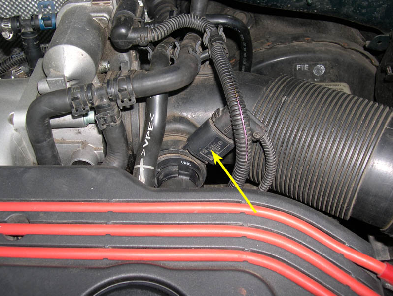
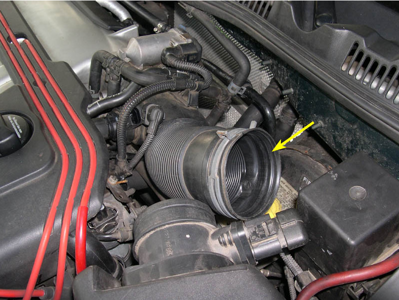
3. Disconnect the harness connector from the PCV heating element on the intake hose between the MAF and throttle body. The harness connector is indicated by the yellow arrow in the picture below.
4. Disconnect the intake hose from the MAF by temporarily removing tension from the spring clamp indicated by the yellow arrow in the picture below and then sliding the hose off of the MAF.
CAUTION: Please be VERY careful when working with the spring clamp. The amount of spring tension applied by the clamp is very large - you do not want to accidentally get a finger caught between the clamp and the hose/MAF when disconnecting the intake hose.
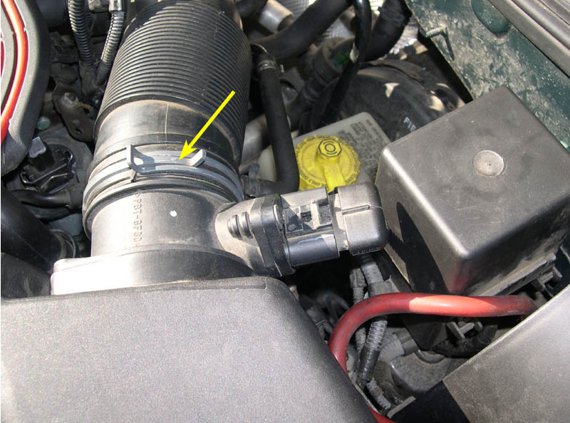
5. Move the disconnected end of the intake hose to the side of the opening in the MAF (as shown in the picture below) so that there will be unobstructed airflow during the compression test. Make sure not to drop anything into the intake hose or leave small objects or tools near the opening - you don't want anything to be unexpectedly sucked into the intake during the test!
6. Use the VR6 spark plug tool to remove the spark plug wire boots from the spark plugs without damaging the boots, as shown below. If you have a MKIV which has plug wires with the integrated pull loops, then you do not need the special tool. Just pull up on the loops to remove the boots from the plugs.
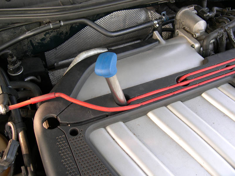
7. Unclip the spark plug wires from the guides in the engine cover trim.
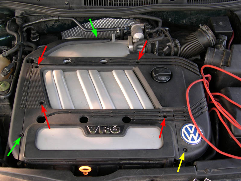
8. Remove the three engine cover trim pieces by removing the T30 Torx screws indicated by the arrows in the picture below. Remove the single screw indicated by the yellow arrow to remove the small trim piece with the VW logo on it. Next, remove the two screws indicated by the green arrows to remove the long, thin trim piece on the passenger's side of the engine. Finally, remove the four screws indicated by the red arrows to remove the main trim piece.
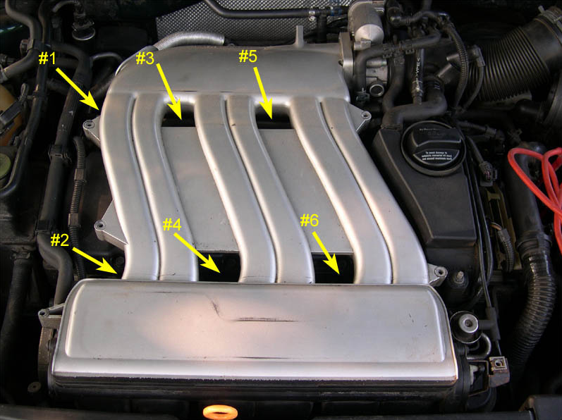
9. The plug locations and cylinder #s are indicated in the picture below (FYI, the firing order on the VR6 is 1-5-3-6-2-4).
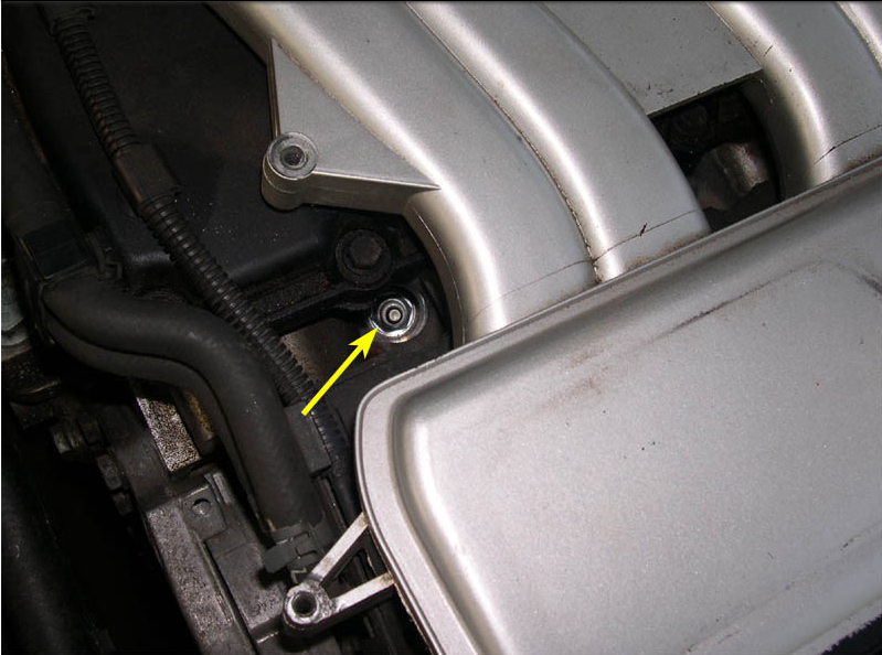
10. The picture below shows one of the spark plugs (cylinder #2) at the bottom of it's recess in the head. Since the plugs sit so deep in the head, sand, dirt and other debris tend to collect around the plugs while driving. Prior to removing the plugs, use compressed air to blow the debris out of the plug recess or it will fall into the cylinder when the plug is removed. This is a VERY important step since sand and other grit which enters the combustion chamber may cause premature wear.
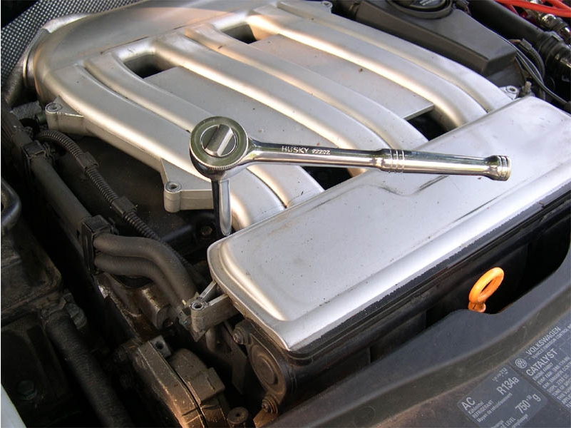
11. Use the 5/8" spark plug socket and long extension to remove ALL of the plugs from the engine, as shown below. It is critical that ALL cylinders are open to air during the test (except for the cylinder that's being tested - this cylinder will have the pressure gauge threaded into it). Make sure to keep the plugs in order as you remove them, or even better, label them with the cylinder # using a piece of masking tape and a marker. This serves two purposes - (1) it ensures that the plug goes back into the cylinder it was removed from, and more importantly, (2) it allows the condition of the plugs to be analyzed and correlated with the compression values for each cylinder. If a particular cylinder has a low compression value, the appearance of the plug can help identify what's leading to poor compression in that cylinder. For example, an oily plug might suggest a ring problem, while an unusually clean-looking plug might suggest a bad head gasket leaking coolant into the cylinder.
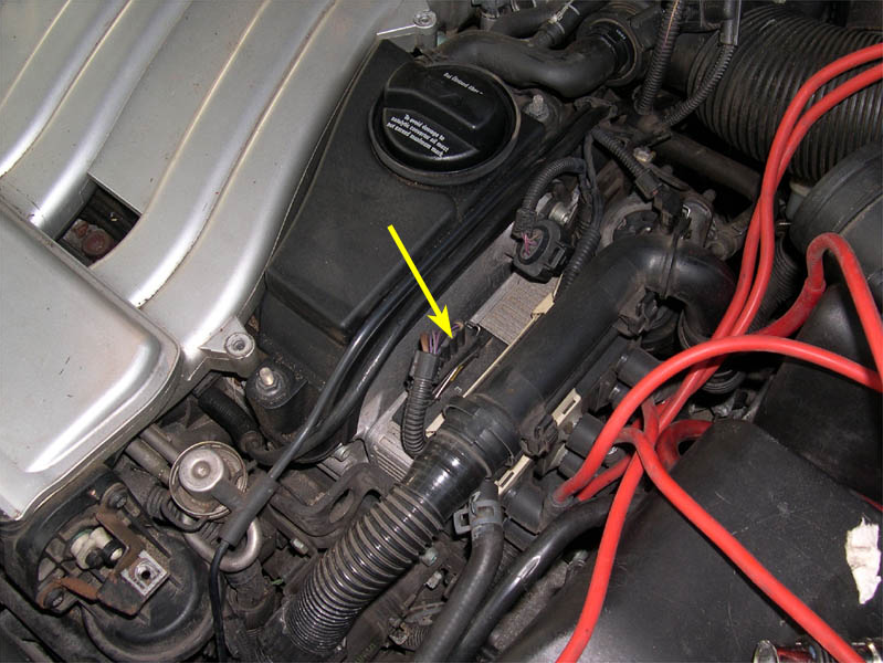
12. Disable the ignition system (make sure ignition is turned off first) by disconnecting the harness connector from the top of the coil pack on driver's side of the cylinder head. The harness connector is indicated by the yellow arrow in the picture below. If you have an early VR6 with a distributor instead of a coilpack, disable the distributor in the appropriate manner.
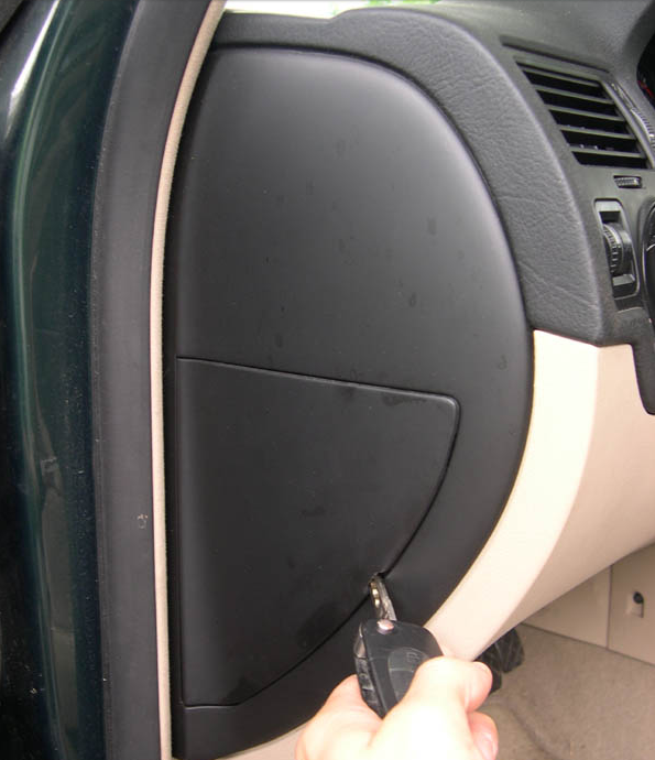
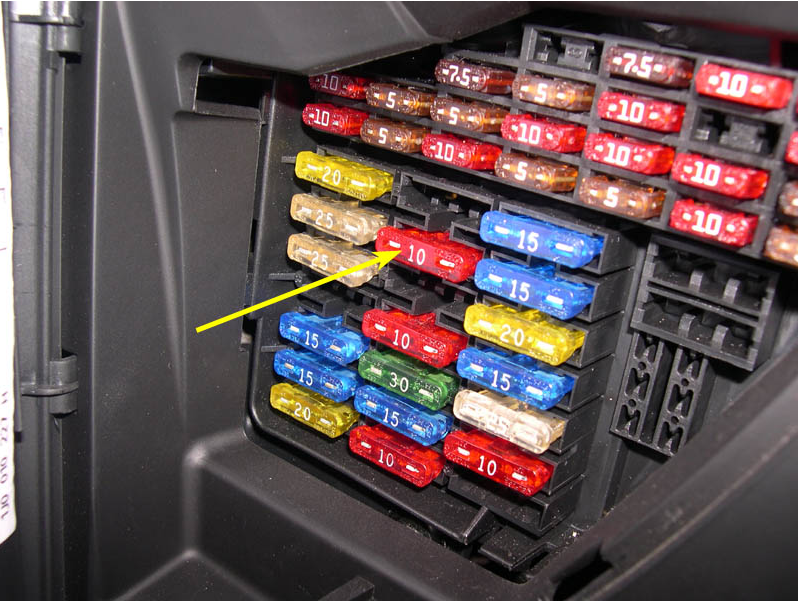
13. With the driver's door open, pop open the fuse panel access door on the side of the dashboard, as shown below. The ignition key works well for this step.
14. Disconnect the voltage supply to the fuel injectors using the procedure appropriate for your vehicle. For the MKIV VR6 (and AFAIK, the other MKIV gasoline engines as well), remove fuse #32 (10A - indicated by the yellow arrow in the picture below) to accomplish this.
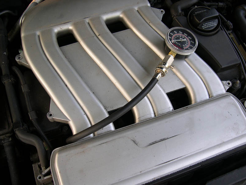
15. Following the specific instructions for your compression tester/pressure gauge, fit the tester into the first spark plug hole. The Craftsman gauge that I used for the test consisted of a rubber extension hose with a steel threaded end that screws into the spark plug hole. The threaded end has an o-ring on it which seats itself against the spark plug opening in the head and makes a seal. All I had to do was thread the end of the hose into the plug hole and hand-tighten by twisting the hose - this provides a good enough seal to accurately perform the test. The picture below shows the Craftsman tester threaded into the plug hole for cylinder #2.
NOTE: It helps to have a helper do steps 16 though 19, but it is not always necessary (it depends on your vehicle and compression tester).
16. Depress the clutch pedal fully.
17. Put the transmission into either neutral or park.
18. Depress the accelerator pedal to the floor (to make sure that there is unobstructed airflow into the engine).
19. Crank the engine over with starter motor until the pressure reading on the gauge stops increasing. With each revolution of the engine, the pressure in the cylinder will increase until a maximum is reached. At this point, the cylinder cannot hold the additional pressure and it will leak out as the engine continues to crank. The MKIV Bentley indicates that the engine should be cranked a minimum of 4-5 revolutions to reach the max pressure, but I just watched the gauge and stopped when I didn't see the pressure increase anymore (about 7-8 revolutions).
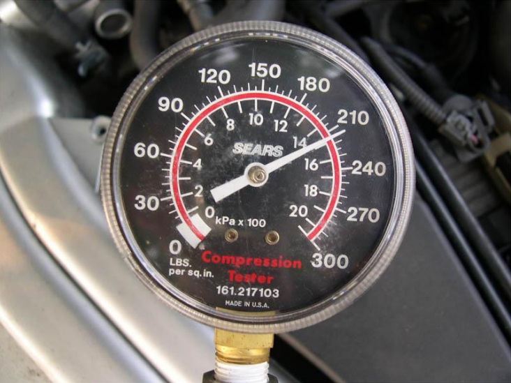
20. If you want to see a video (Windows Media Format, 750kb) I took of the gauge during the test, you can find it here - Compression Test Video. The picture below shows a close-up of the gauge after one of the tests. This particular cylinder had a max pressure of 215 psi (was actually 209 psi - I checked the calibration of the gauge after the test and it was a little high).
21. After performing the test, record the cylinder # and pressure reading, release the pressure from the gauge (follow the specific instructions for your particular gauge), remove the gauge from the spark plug hole and then repeat the testing procedure (steps 15 through 19) for each remaining cylinder.
22. After the compression values have been checked in all cylinders, reassemble everything by following steps 3 though 14 in reverse. If you have a torque wrench, make sure to torque the spark plugs to 18 ft-lbs (25 Nm) when reinstalling them. If the plugs haven't been changed in a while, now is a good time to replace them.
23. Finally, on an OBDII car, such as the MKIV VR6, performing the above test will cause a CEL to light up and diagnostic trouble codes (DTCs) to be stored in the ECM (engine control module) memory due to the ignition system being disabled and engine components being disconnected. This may also apply to an OBDI car as well, but I'm not sure. A VAG-COM scan of my car's ECM following the test revealed the following information ...
VAG-COM Version: Release 303.1
Control Module Part Number: 021 906 018 B
Component and/or Version: MOTRONIC ME7.1 G V06
Software Coding: 00000
Work Shop Code: WSC 00066
6 Faults Found:
17645 - Fuel Injector for Cylinder 1 (N30): Open Circuit
P1237 - 35-10 - - - Intermittent
17649 - Fuel Injector for Cylinder 5 (N83): Open Circuit
P1241 - 35-10 - - - Intermittent
17647 - Fuel Injector for Cylinder 3 (N32): Open Circuit
P1239 - 35-10 - - - Intermittent
17650 - Fuel Injector for Cylinder 6 (N84): Open Circuit
P1242 - 35-10 - - - Intermittent
17648 - Fuel Injector for Cylinder 4 (N33): Open Circuit
P1240 - 35-10 - - - Intermittent
17646 - Fuel Injector for Cylinder 2 (N31): Open Circuit
P1238 - 35-10 - - - Intermittent
24. To turn off the CEL AND erase the codes from the ECM memory, clear the codes with a VAG-COM or other suitable OBDII scanner. Note that disconnecting the battery for 20 minutes or so will turn off the CEL, but it will not erase the codes from memory. In fact, doing so will add an additional code to the list - 18010/P1602 - Power Supply Terminal 30: Voltage Too Low.
EVALUATION OF TEST RESULTS
According to the MKIV Bentley manual, the compression specifications for the 12v VR6 engine are as follows (the values you obtain during your test will depend on both the condition of the engine and the accuracy of the pressure gauge used):
- new ------------------------------------------------------ 10 to 13 bar (147-191 psi)
- wear limit ------------------------------------------------ 7.5 bar (110 psi)
- maximum difference between cylinders ------------------ 3 bar (44 psi)
Here's a quote from the MKIV Bentley manual (page 15d-2) which talks about compression values which are lower than spec ...
"Low compression suggests poorly sealed combustion chambers. Compression pressures which are relatively even but below specifications indicate worn piston rings and/or cylinder walls. Low but erratic values tend to indicate valve leakage. Dramatic differences, such as good values in some cylinders and very low values in one or two cylinders are the sign of a localized failure, such as a burnt valve or a failed cylinder head gasket."
Most Popular
-
1
-
2
-
3
-
4
-
5

